
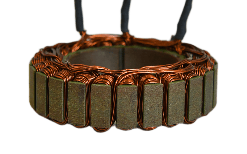
A robot joint motor is not necessarily a frameless motor. Depending on the mechanical architecture, a robotic joint may use a conventional servo motor, a compact BLDC motor or a fully integrated actuator.
But when space becomes tight, a frameless torque motor starts to make a lot of sense. We discussed the reasons behind this in more detail in our earlier article on why frameless torque motors are used in robotic joints and exoskeleton actuators.
Instead of supplying a complete motor with its own housing, shaft and bearings, the stator and rotor are integrated directly into the customer’s mechanism. For a robotic joint, that means the motor can be designed around the available diameter, axial length, bearing arrangement, gearbox and cable routing rather than forcing the whole joint to fit around a standard motor frame.
That flexibility is valuable, but it also changes the way the motor should be selected.
For a robotic joint project, we would normally start with the joint requirements and available mechanical space, not simply with a motor power rating.
Start With the Joint, Not the Motor
A statement such as “we need a 400 W motor” does not tell us very much about the actual joint.
Two motors with the same rated power can behave very differently if one application needs high torque at low speed and the other operates much faster.
The more useful starting points are:
- continuous torque
- peak torque
- operating speed
- acceleration and deceleration
- duty cycle
- gearbox ratio, if a reducer is used
- available motor diameter and length
Continuous and peak torque should also be treated separately.
A robot may only need peak torque for a short acceleration or load disturbance, while the continuous torque requirement determines how much heat the motor must dissipate over time.
This distinction often has a bigger influence on motor size than the nominal power figure alone.
There is another practical point: the motor should be evaluated together with the transmission.
A joint requiring high output torque does not automatically require a motor with the same shaft torque. If a strain-wave, planetary or cycloidal reducer is used, the motor can operate at a higher speed and lower torque. The reduction ratio, efficiency and required joint speed then become part of the motor-sizing calculation.
So the useful question is not simply:
“How much torque does the motor produce?”
It is:
“What torque and speed must the motor produce inside this particular joint architecture?”
Mechanical Envelope Is Usually an Early Design Constraint
With a frameless motor, outer diameter, inner diameter and axial length are not secondary dimensions. They are part of the electromagnetic design.
This becomes especially important in compact robotic joints.
A larger hollow bore, for example, can make it much easier to route encoder wiring, power cables, communication lines or other services through the joint. But if the outside diameter is already fixed, increasing the bore also leaves less radial space for the active motor structure.
That is a real design trade-off.
Likewise, increasing axial length may provide more room for active material, but the joint may have a strict width limit.
For an early motor evaluation, we therefore normally want to know three dimensions as soon as possible:
maximum OD, required ID and maximum axial length.
These three values often tell us more about what motor architecture is realistic than the nominal wattage.
Continuous Torque Is Also a Thermal Question
This is one of the areas where a frameless motor differs from a conventional housed motor.
The customer’s structure effectively becomes part of the motor’s thermal system.
The stator is typically mounted directly into the joint housing, so heat generated in the windings must pass through the stator and mounting interface into the surrounding structure.
As a result, the same electromagnetic motor design can have different practical continuous-torque capability under different installation conditions.
An aluminium housing with good contact to the stator will behave differently from a structure with a poor thermal path. Ambient temperature, duty cycle and any forced or liquid cooling also matter.
That is why we would be cautious about selecting a frameless motor only from a catalogue continuous-torque figure.
For a robotic joint, a better question is:
“Under what thermal conditions was that continuous torque achieved, and how close are those conditions to the real actuator?”
Peak torque is mainly an electromagnetic and current-limit question.
Continuous torque is very often a thermal-integration question as well.
Inner-Rotor or Outer-Rotor?
Both arrangements can work well in robotic actuators, and neither is automatically better.
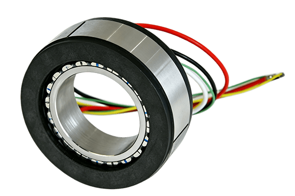
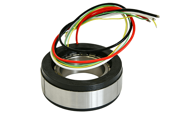
In an inner-rotor frameless motor, the rotor runs inside the stator. This is a familiar servo architecture and can be attractive where dynamic response and relatively low rotor inertia are important.
An outer-rotor frameless motor places the rotor around the stator. Because torque is produced at a larger effective radius, this architecture can be useful when a designer wants relatively high torque in a short axial package.
The choice should still come back to the actuator.
If the design is strongly limited in axial length, an outer-rotor concept may deserve consideration.
If rotor inertia, speed or a particular bearing arrangement is more important, an inner-rotor architecture may fit better.
The important point is not to choose the motor topology first and then design the joint around it.
For a custom robotic joint, the mechanical envelope and required performance should lead the decision.
Hollow Bore, Feedback and Cable Routing Should Be Considered Together
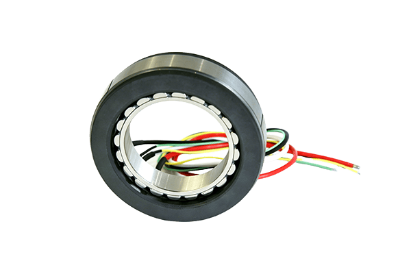
A hollow centre is one of the useful features of many frameless motor designs, particularly in robotic joints.
But the bore is rarely there just for appearance.
The same central space may need to accommodate:
- encoder cables
- motor power cables
- communication wiring
- brake wiring
- pneumatic or hydraulic lines
- the actuator output shaft or transmission components
This is why cable routing should be discussed early rather than after the motor dimensions have already been fixed.
Feedback is another part of the same integration problem.
Simple commutation may use Hall sensors, while a high-precision robotic joint will normally require more accurate rotor or joint-position feedback from an encoder, resolver or another position-sensing system.
The required feedback method affects the available space, wiring and control architecture.
Motor, encoder and drive should therefore be considered as one motion system rather than three unrelated components.
Torque Ripple Matters More at Low Speed
A motor that looks perfectly acceptable at several thousand rpm may behave differently when the robot is moving slowly or holding position.
Robotic joints often work at low speed, reverse direction frequently and make small positioning movements. Under these conditions, characteristics such as cogging torque and torque ripple become easier to notice.
That can affect:
- low-speed smoothness
- positioning behaviour
- vibration
- acoustic noise
- control stability
For this reason, selecting a frameless motor purely from maximum torque density can be misleading.
A slightly different electromagnetic design may be preferable if the application places more emphasis on smooth low-speed operation or precise force control.
Again, the correct choice depends on what the joint actually needs to do.
What We Normally Need for an Initial Evaluation
For a new robotic joint project, a complete finished drawing is not always necessary at the beginning.
An initial evaluation can often start from a relatively small set of information:
- Continuous torque
- Peak torque and allowable peak duration
- Motor operating speed
- Joint output speed
- Gear ratio or reducer type, if applicable
- DC bus or motor voltage
- Maximum motor outer diameter
- Required hollow-bore diameter
- Maximum axial length
- Duty cycle and ambient conditions
- Encoder or feedback requirement
- Estimated annual quantity
If a project is still at an early design stage, even a torque-speed requirement together with the available OD, ID and axial length is enough to begin a meaningful discussion.
From there, winding, voltage, current, rotor architecture, thermal design and sensor arrangement can be refined around the actual actuator.
A Frameless Motor Is Part of the Joint, Not Just a Component Inside It
That is probably the most useful way to think about frameless motors for robotics.
Once the conventional motor housing, shaft and bearings are removed, the boundaries between the motor and the actuator become less clear.
The joint housing becomes part of the motor’s thermal path. The actuator bearings influence rotor support. The central bore affects both mechanical integration and electromagnetic space. The gearbox determines the motor operating point, while the encoder and drive determine how that torque is controlled.
This is why selecting a frameless torque motor is usually an integration exercise rather than a catalogue-selection exercise.
For custom robotic joint projects, TorqueBank can evaluate the motor around the required torque-speed profile, available installation envelope, hollow-bore dimensions, voltage, cooling conditions and feedback arrangement. More information about our development approach is available in Custom Frameless Motor Solutions for Robotics and Exoskeletons.
Providing these parameters early makes it much easier to determine whether an existing motor platform can be adapted or whether a more application-specific motor design is appropriate.